We all know that I2C bus is a simple, two-way two-wire synchronous serial bus developed by Philips company. It only needs two wires to transmit information between devices connected to the bus.
I2C bus introduction
I2C combines the advantages of SPI and UART. With I2C, you can connect multiple slaves to a single master, such as SPI, and have multiple masters control one or more slaves. This is useful when you want multiple microcontrollers to record data to a single memory card or display text to a single LCD.
Like UART communication, I2C only uses two lines to transmit data between devices:
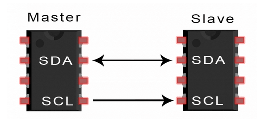
SDA (serial data) - a line for sending and receiving data from the master and slave stations.
SCL (serial clock) - the line that carries the clock signal.
I2C is a serial communication protocol, so data is transmitted bit by bit along a single line (SDA line).
Like SPI, I2C is synchronous, so bit output is synchronized with bit sampling through the clock signal shared between the master and slave. The clock signal is always controlled by the host

How I2C works
When I2C is used, the data is converted into messages and messages are decomposed into data frames. Each message has an address frame that contains the binary address of the slave and one or more data frames that contain the data being transmitted. The message also includes start and stop conditions between each data frame, read / write bits and ACK / NACK bits:

Starting condition: before the SCL line is switched from high level to low level, the SDA line is switched from high level to low level.
Stop condition: after the SCL line is switched from low level to high level, the SDA line is switched from low level to high level.
Address frame: a unique sequence of 7 or 10 bits for each slave station to identify the slave station when the master station wants to communicate with it.
Read / write bit: a single bit that specifies whether the master device sends data (low voltage level) to the slave device or requests data (high voltage level) from the slave device.
ACK / NACK bit: each frame in the message is followed by an answer / no answer bit. If the address frame or data frame is successfully received, the ACK bit is returned from the receiving device to the sender.
address
I2C does not have a slave selection line like SPI, so it needs another way to let the slave know that data is being sent to it, rather than another slave. It does this through address. The address frame is always the first frame after the start bit in the new message.
The master sends the address of the slave it communicates with to each slave it connects to. Each slave then compares the address sent from the master with its own address. If the address matches, the low voltage ack bit is sent back to the host. If the address does not match, the slave does nothing and the SDA line remains high
Read / write bits
The address frame includes a bit at the end to inform the slave whether the master wants to write data to it or receive data from the master. If the master wants to send data to the slave, the read / write bit is low. If the master requests data from the slave, the bit is high.
Data frame
After the master detects the ACK bit from the slave, it is ready to send the first data frame.
The data frame is always 8-bit long and sent first with the most significant bit. The ACK / NACK bits of each data frame are followed to verify that the frame has been successfully received. Before sending the next data frame, the master or slave must receive the ACK bit (depending on the person who sent the data).
After all data frames have been sent, the master device can send a stop condition to the slave device to stop transmission. The stop condition is that after the conversion from low level to high level on the SCL line, the SDA line changes from low level to high level, and the SCL line keeps high level.
I2C data transmission steps
1. The host sends data to each connected slave device, then switches the SDA signal from high to low, and then switches the SCL from high to low

2. The master sends to each slave the 7 or 10 bit address of the slave it wants to communicate with, as well as the read / write bit:
3. Each slave device compares the address sent by the master device with its own address. If the address matches, the slave device returns the ACK bit by pulling the SDA line one bit lower. If the address of the master does not match the address of the slave, the slave keeps the SDA line high.

4. Main equipment sends or receives data frame:

5. After each data frame is transmitted, the receiving device returns another ack bit to the sender to confirm that the frame is successfully received:

6. To stop data transmission, the host sends a stop condition to the slave by switching the SCL to high before switching the SDA to high:

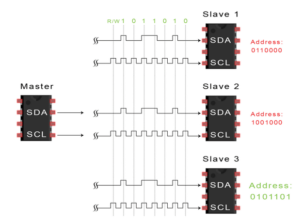
Single master with multiple slaves
Since I2C uses addressing, multiple slaves can be controlled from a single master. Using a 7-bit address, you can use 128 (27) unique addresses. Using a 10 bit address is not common, but provides 1024 (210) unique addresses. To connect multiple slaves to a single master, connect them like this, using a 4.7K ohm pull-up resistor to connect the SDA and SCL wires to the VCC:

Advantages and disadvantages of I2C
Compared with other protocols, I2C sounds very complex, which is not easy to be implemented in the program, resulting in data loss, no response, "dead" and other problems. But there are many advantages:
 Advantage
Use only two wires
Support multiple master servers and multiple slave servers
ACK / NACK bits confirm that each frame has been successfully transmitted
Hardware is not as complex as UART
Well known and widely used protocol
shortcoming
Data transfer rate slower than SPI
Data frame size is limited to 8 bits
Implement more complex hardware than SPI